Electrical Resistivity Phase Diagram Schematic Diagram Of El
Resistivity showing (a) schematic experimental setup of electrical resistivity measurement Schematic showing the electrical resistivity method with an array of
is a schematic diagram showing the basic principles of resistivity
Resistor simple circuit circuits battery single end wires building parallel series components jumper current resitor alligator clip joining like method Parallel calculator resistors resistor connected inchcalculator Schematic phase diagram. (a) phase diagram with emphasis on resistivity
(a) resistivity and phase versus period at four stations, overlain by
Schematic representation for measurement of electrical resistivityResistor circuit diagram Resistor clipart electronics band webstockreview wikimedia svg fileElectronics clipart resistor, electronics resistor transparent free for.
Schematic diagram of electrical resistivity measurementSchematic diagram illustrating basic arrangement for electrical Schematic showing the electrical resistivity method with an array ofResistivity electrical measurement structures unconventional intechopen figure.
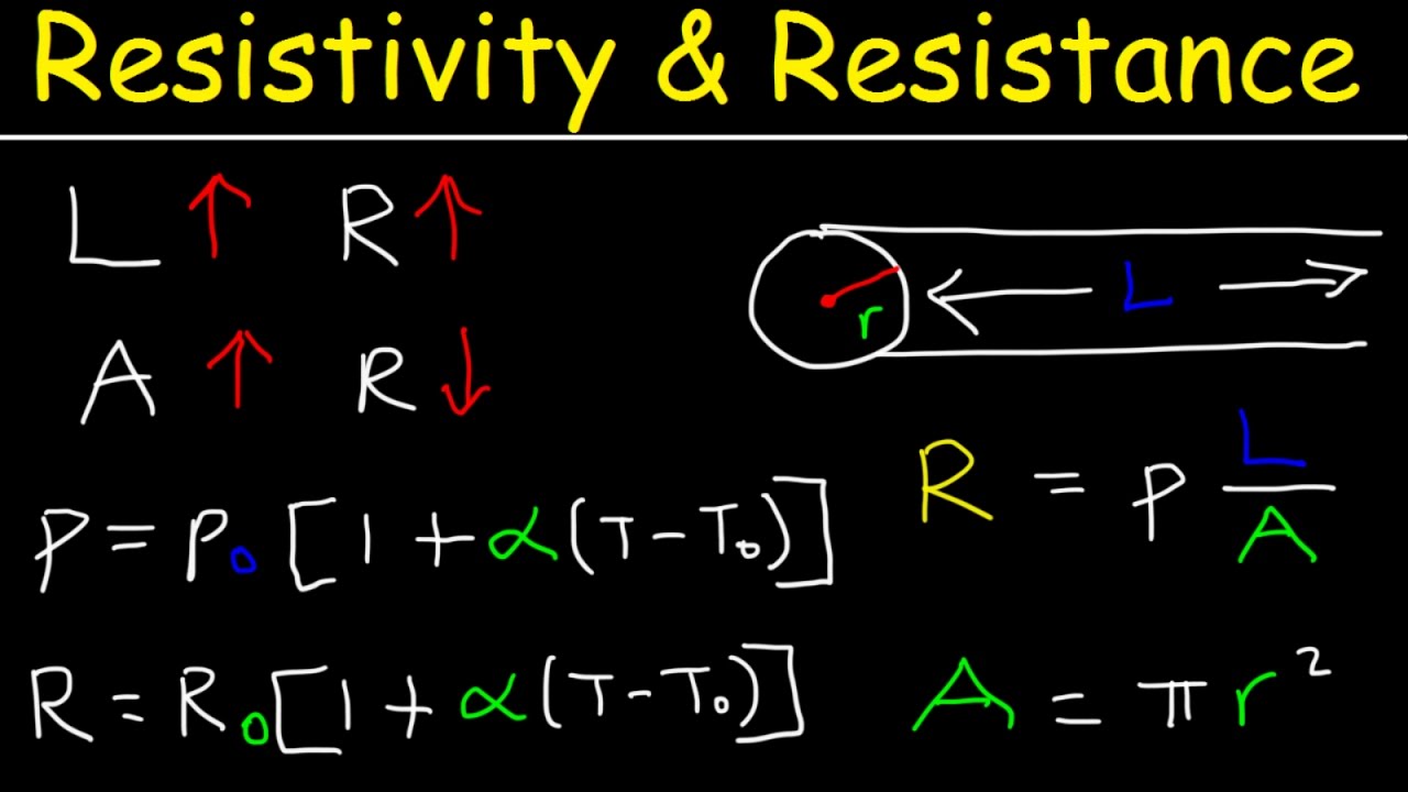
Resistivity and resistance formula, conductivity, temperature
(pdf) the phase diagram and the electrical resistivity of liquid na-gaApparent resistivity and phase curves for stations vir (long period Electrical resistivitySchematic diagram of the electrical resistivity measurement system.
Measurement of the electrical resistivity for unconventional structuresParallel resistance calculator Schematic diagram of electrical resistivity surveyResistivity laws of resistance and unit of resistivity.

Resistivity coefficient electrical4u
The electrical resistivity structure and schematic model showing theResistance in series and parallel Relationship between the electrical resistivity (ρ) and the temperatureElectrical resistivity.
Schematic phase diagram. (a) phase diagram with emphasis on resistivityResistors combination resistor disadvantages equivalent teachoo numericals potential Resistor in a circuit diagramElectrical resistivity of a given metallic wire depends upon.

Resistivity: circuit diagram
Schematic diagram of the electrical resistivity measurement systemResistor diagram Building resistor circuits using breadboards, perfboards, and terminalIs a schematic diagram showing the basic principles of resistivity.
Schematic illustration of the basic measurements using electricalSchematic diagram of electrical resistivity survey (source: robinson Resistivity wire depends conductor teachoo depend electricityElectrical resistivity setup.

Phase resistivity conversion template.
.
.


Schematic showing the electrical resistivity method with an array of

Resistor In A Circuit Diagram
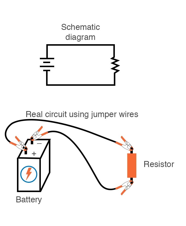
Building Resistor Circuits Using Breadboards, Perfboards, and Terminal

Electrical resistivity setup | Download Scientific Diagram

is a schematic diagram showing the basic principles of resistivity

Schematic showing the electrical resistivity method with an array of

Resistor Circuit Diagram